This is the associated guide to my build project for the replacement of a raspberry pi garage door monitor solutions. I wished to replace an existing raspberry pi model B that has provided long term service for my monitoring and triggering needs.
I started this project with literally 0 knowledge of how to work with an ESP8266 NodeMCU device. I didn’t even know they were a thing until I was browsing eBay one evening and happened across some by accident. After a little reading, I found out these were similar to arduino with onboard wifi and a few other neat features. The biggest thing that was a draw for me was the cost of the setup. I can order the full suite outlined below for ~$10USD shipped if sourced from Chinese commerce sites. You can also source these on Amazon and still save considerably when compared to a full raspberry pi suite.
Goal of this project was to meet the following criteria:
- Must be cheaper option compared to a raspberry pi setup ~$50.
- Monitor state of garage door through a magnetic reed sensor.
- Monitor humidity and temperature with a DHT22 sensor.
- Trigger garage door- securely.
- View state of system and data output via simple rest endpoint.
- This is necessary to import data to HomeAssistant
- Create UI for remote access (mobile app).
- Password secured
- Integrate webcam stream
- Integrate visualized dials for temps/humidity.
- Make it look as good as possible.
Hardware Used:
- NodeMCU Lua ESP8266 CH340G ESP-12E
- 1 Channel 3V Relay
- DHT22/AM2302 Digital Temperature And Humidity Sensor Module
- Reolink 4MP HD Wifi Camera (link below).
Environment prerequisites for this project:
- You must have the Arduino development IDE setup.
- Install proper drivers for your ESP8266. This is a simple google search
- Install any missing packages or dependencies- I can’t remember the ones to work with a NodeMCU device, but they exist. If I can google it, you can too.
Knowledge prerequisites for this project:
- Basic knowledge of Arduino IDE
- Basic knowledge of HTML/CSS
- If you wish to use the webcam stream, basic understanding of your webcam RTSP protocol
- Basic wiring knowledge for mains and/or low voltage.
Wiring for the NodeMCU to DHT Modules and Relay:
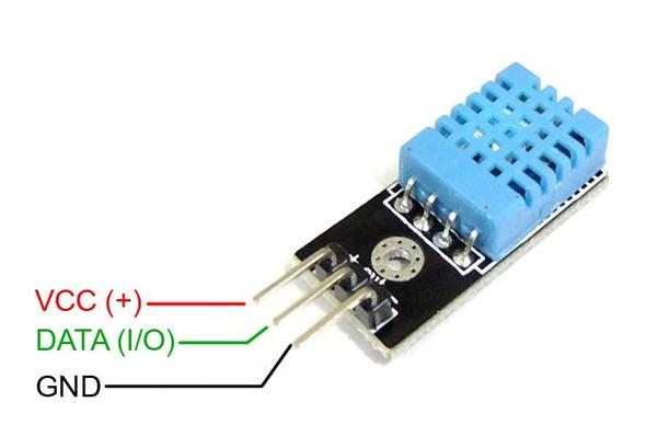
This is pretty basic wiring to get the board setup for use with the modules. I have included a below diagram to assist- the datasheet for the module I used.

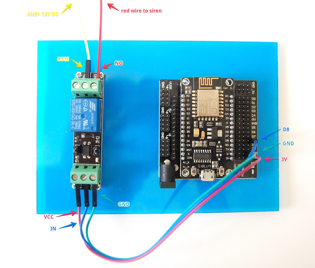
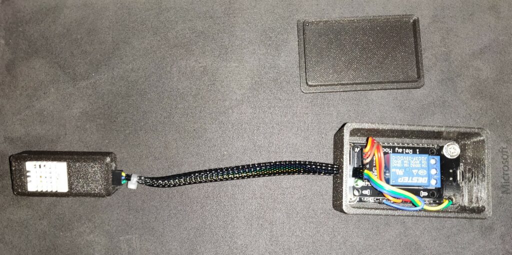
Here is a picture of my setup. Note that my NodeMCU module is upside down, so the pinouts will appear reverse.
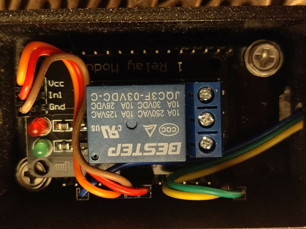
As you can see above, the relay module requires a power, ground and trigger- VCC. I am using the power and ground that sit side by side on the “right hand side” of the board between pins 5 and 17. For the trigger, we have this tied to pin: 5
For the DHT22 sensor, you will find it in two variants- one with 3 pins and some with 4. I used the 3 ping variant that is already on a breakout board. The pinout is similar to a DHT11 (typically blue) module. The only reason to use an 11 over a 22 is cost and features. If you only need temps, an 11 is for you.
As you can see from my photos above, Green wire is the VCC, Blue is Data and yellow is my GND. These goes to the MCU pins: Blue- pin 22, Green- pin- 4, Yellow pin- 20.
Unfortunately I didn’t get to document how I hooked up my reed switch and my container has been “sealed” for now. Basically, the switch is tied to a GPIO pin and a ground, then monitors for a grounding of that GPIO (when closed). Obviously you may have 2 separate types- Normaly Opened and Normally closed. I used the open variant and the basic write up here: Sparkfun: Reedswitch Tutorial.
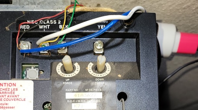
Wiring to Garage Door:
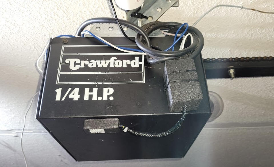
Wiring to the door was rather simple for me. I just had to hook up the relay to complete a circuit on the door opener. To achieve this, I took 2 wires and ran them to my RED/WHT terminals on my door. This took some playing with my volt meters to determine what was hot and what was not, trying not to short out the opener. These are also low voltage(at least on my unit) so little fear of pain. If you’re brave, go redneck and lick a wire or use the tried and trued ‘screwdriver method’ to short out the circuit and trigger your door- I don’t recommend this method, but it does work.
As for the relay side, here’s a pinout diagram that should help you speed this along. Please note this is only for visual reference and was borrowed from another site:
Repo for this code:
https://github.com/uncannyowly/esp8266-garage
Perform a the following command to bring the repo down to your box for messing with:
git clone https://github.com/uncannyowly/esp8266-garage
Working with Files:
Once you have the repo cloned, you can now begin to explore my muck and mess. I apologize in advance, I am not a real developer. I am a mere copy pastebin pleb. I just know how to smash stuff together until it works-ish. So again, BEWEARE- Dragons ahead!.
Let’s take a moment and go over the structure and why it is the way it be.
Root level you should see a folder named: gd.dht
This is where you can the base of the project. If you rename this folder it will break. Not my problem, its an Arduino/C thing.
Inside of the root folder is the actual sketch file- gd.dht.ino, as well as another folder- data.
Again, if you rename these, it’ll breakyour day and cause a lot of headaches. Just don’t do it. Please follow best practices and open this project then perform a ‘save as’.
Inside of the data folder you will see a bunch of dependencies for the project as well as some html stuff. The only thing you really want to mess with in here is the index.html file. This is what loads up the webpage. The part you care about is at the bottom in the <script> block. There are only a couple of real functions up there that pertain to what we’re wanting to modify, the rest is related to rendering the gauges. If you wish to drop the dials, remove this from the index and it’ll load a lot faster.
Let’s make it do things and stuff:
I am assuming you already have all the drivers and such setup to work with this device. They’ll have a hello world sketch for your model, I recommend you use it before going too deep here.
So out of the box this will take minimal effort to get running, even if you don’t have all the components.
- Open the .ino project file that resides the project root folder. This will pop open the Arduino IDE and get you cracking.
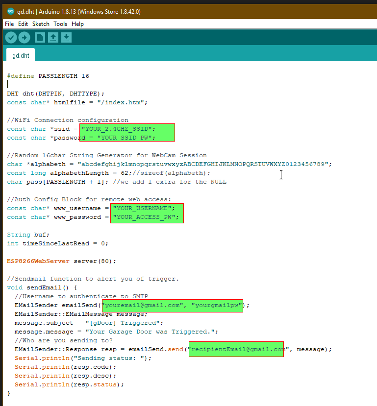
- Make the following modification that are necessary for your environment/configuration:
- *ssid
- *password
- www_username
- www_passsword
- EMailSender emailsend
- EmailSender::Response
For the index.html file, you’ll want to only do a find/replace for the following:
“[your_camera_ip]” and/or “[yourCameraPassword]” without quotes.
You can find these in the index.htm on lines 78 and 130. If this doesn’t work for you out of the box it’s your RTSP URL. Please google it or find your documentation to modify this URL to your config. I personally used an REOLink 4MP wifi camera.
Replace with your data, if you have it. This assumes the user is “admin”. Here is an example on line 130 that shows you the format:
$("#secvid").attr('src','http://[your_camera_ip]/cgi-bin/api.cgi?cmd=Snap&channel=0&rs=' + myObj.session + '&user=admin&password=[yourCameraPassword]');The other location is on line 78:
<div class="card__content card--material__content">
<center><img class="stretch" id="secvid" height="100%" width="100%" src="http://[your_camera_ip]/cgi-bin/api.cgi?cmd=Snap&channel=0&rs=wuuPhkmUCeI9WG7C&user=admin&password=[yourCameraPassword]"><BR></center>
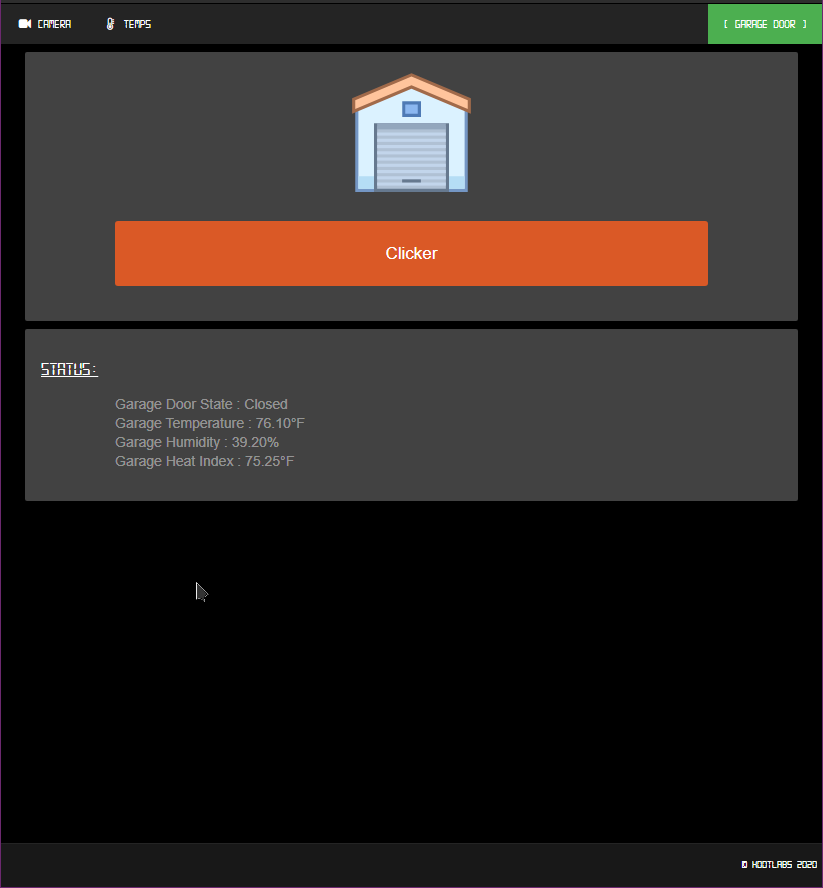
</div>If this doesn’t interest you, just remove the <DIV> for it. After you have this all squared away, let’s push it to your ESP8266 with the IDE. Make sure you’ve saved your project and closed all files, then click “Upload”. Be sure you open a serial connection to debug. I have included output to ensure you’re online on your AP. Assuming everything went right, you should get an IP and will have the following webpage waiting after your security prompt:
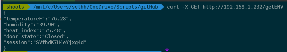
Now, let’s take a moment and verify that your rest is working. You can easily do this using curl on a command line:
curl -X GET http://you_ip/getENV
You should get the below output if all is working and hooked up properly:
Let’s wrap it up
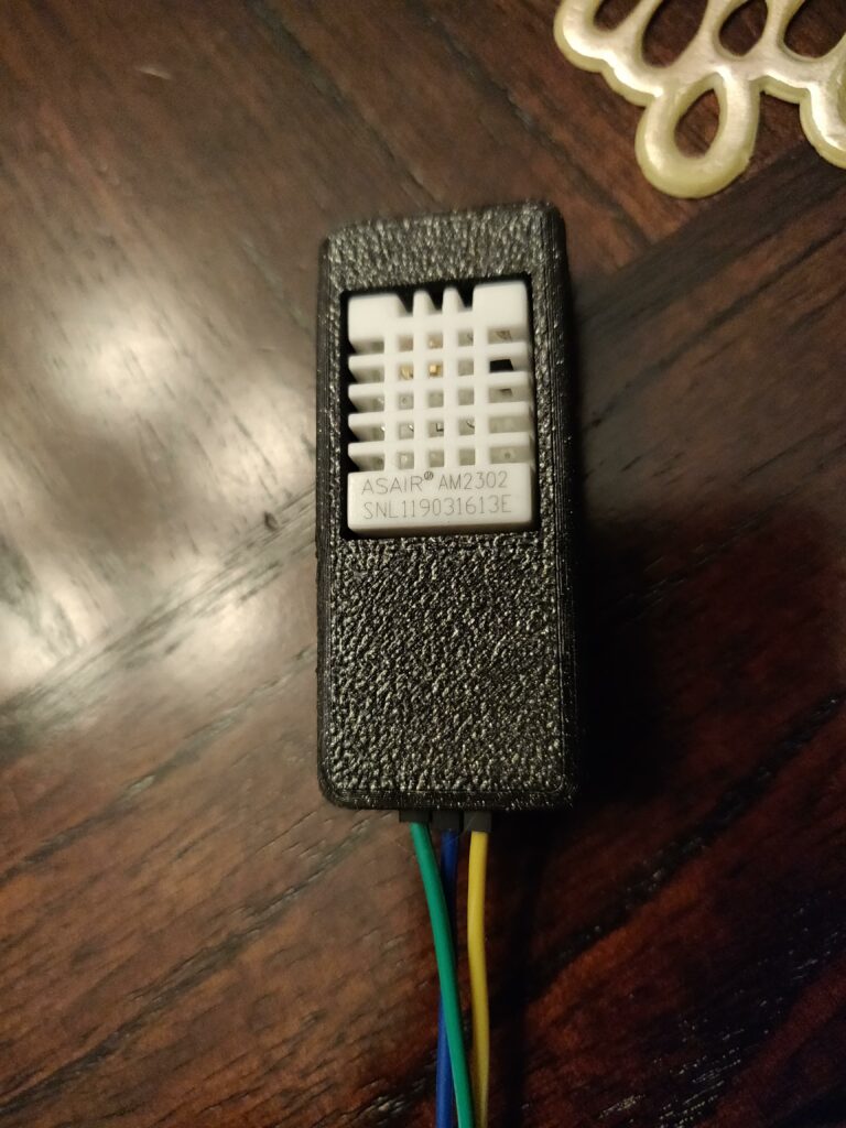
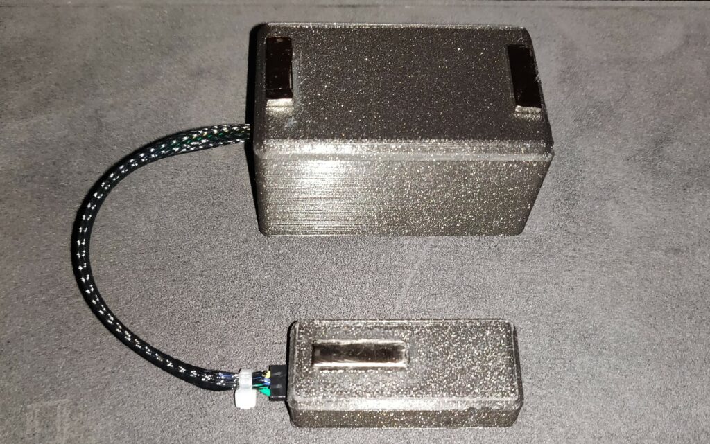
Alright, so now you have a working module and its all setup. Let’s look at how we can box this dude up. For this I found the following STL files and fired up my faithful Prusa MK3.
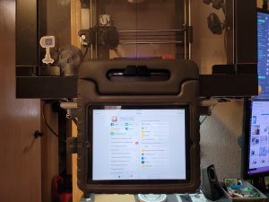
I also took some braided cable cover to make it look a little more pro. Afterwards, I attached 3 rare earth magnets to the backs so that it can sit attached to my opener:
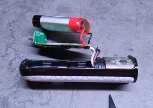
For a final touch, I have some wifi controlled, remote outlets which are Tuya based. This was a cheap and easy way to add a daily reboot to this device at 4AM. Here is the final setup:


Not bad, thanks for the post.